The patented inclinometer described here is designed to correct bias and misalignment drift from all sources. The basic idea is to apply a generations old method used by carpenters and builders to check bubble levels, by turning the tool 180 degrees on the measured surface. If the bubble shows the same result, it is working correctly. Otherwise, it indicates an error of alignment, which equals half the peak to peak difference in the positions of the bubble. In this implementation, the servo inclinometer seats on a rotary disk with its input axis IA parallel to a surface, which is turned 180 degrees between two diametrically opposed positions (1) and (2) for the bias correction operation (figure 5).
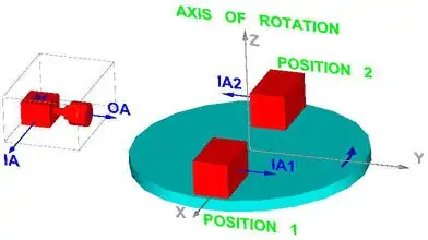
FIGURE 5 The servo-inclinometer on a rotary base
The output of the inclinometer for zero input (inclinometer base on a perfectly horizontal surface) is made of two components:
- The bias error VB, defined as an output independent from the inclinometer position. Internal forces applied on the proof mass by the elastic suspension mostly cause this output, in addition to amplifiers offset.
- The misalignment error angle ,, due to the base of the sensor not being perfectly parallel to its sensitive axis. This causes a voltage output V, proportional to the misalignment angle , (for small angles sin,~,).
If the rotating base in figure 5 turns in a perfectly horizontal plane, it is evident that both the bias output VB and the misalignment output V, of the inclinometer remain the same in both positions (1) and (2): V0=VB+V,
Now suppose that the rotating base is tilted by an angle  around the Y axis, and we repeat the same procedure (figure 6). It becomes evident that by rotating the sensor as shown, the magnitude of the angle remains the same in both positions, while the direction of the sensitive axis is inverted, thus inverting the polarity of the voltage output Vv. The voltage outputs in positions (1) and (2) can then be found by superposition to be:
V1= V0+ Vv= VB+V,+Vv and V2=V0-Vv= VB+V,-Vv
Finally, subtracting the outputs of positions (1) and (2): V1-V2=2Vv leading to the desired result Vv=(V1-V2)/2
In words, the bias and misalignment errors can be completely eliminated from the equation, leaving only the real tilt result; in effect, an auto-zero feature.

The Auto-Zero Force-Balance Inclinometer
FIGURE 6 Rotary base tilted
In order to put the described principle to practice, some basic requirements need to be fulfilled:
- The mounting surface of the base in position (2) should be parallel to that of position (1), and to the mounting surface of the sensor housing.
- Since the inclinometer is in fact an accelerometer, the instrument should be in rest during the bias correction operation, and vibration should be avoided.
- The readings in the measurement positions should be taken after the inclinometer output reached the steady state level.
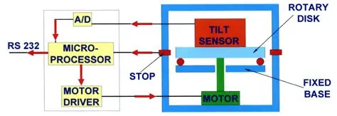
The described principle has been implemented in several different ways. The preferred one uses a servo-inclinometer mounted on an accurately machined disk, which in turn seats on high accuracy bearing balls sandwiched between it and a second plate, in a thrust-bearing configuration. A motor drives the disk between two stops at 180o from each other. At each of the stops a reading is taken, converted using an A/D of sufficient resolution, accuracy and speed, stored in memory, and the final result computed using a microprocessor. The digital output is serially transmitted in RS-232 or other format (figure 7).
The Auto-Zero Force-Balance Inclinometer
FIGURE 7 An implementation of the principle
After the auto-zero operation, the inclinometer is turned back to its initial position, and it continues measuring tilt as a conventional tilt sensor starting from a bias corrected output.
The auto-zero operation can be repeated as needed, or periodically at pre-adjusted time intervals.
A second implementation is a dual-axis device, in which two inclinometers are mounted on the rotary base, to measure and bias-correct in two perpendicular directions. In both the single and dual axis devices, a third accelerometer can be used to sense any movement or vibration appearing during the auto-zero operation, which could produce a false result. In that case, a signal is sent to the micro-processor to repeat the operation. Figure 8 and 9 show the single and dual axis devices.
The Auto-Zero Force-Balance Inclinometer
FIGURE 8 The single axis auto-zero inclinometer
The Auto-Zero Force-Balance Inclinometer
FIGURE 9 The dual axis auto-zero inclinometer
A third embodiment of the invention uses a simpler bearing driving a low-cost mass produced inclinometer. This arrangement makes possible to use low-cost inclinometers in cost-sensitive leveling applications by vastly improving the accuracy of small angle readings.
Applications of the auto-zero force balance inclinometer
Some of the applications of the new inclinometer:
- The single axis device has been used in fire-control systems of tanks, showing accurate operation down to a few arc-seconds under repeated shocks of thousands of g’s, vibration and temperature extremes. It is also currently considered for its use in leveling the transporters used by NASA to carry spacecraft to the launching pad.
- The dual-axis device is being used as horizontal reference for the radar antenna of the
Arrow anti-missile systems, where a 0.0028° accuracy over the full temperature range
and over a period of years is required. - Low range MEMS accelerometers could be used for less demanding leveling and low
range tilt measurement, if the bias stability is improved. One application used a
MEMS accelerometer mounted on a simple rotary device to level diamond polishing
tables, achieving an order of magnitude accuracy improvement.
Other cases of potential applications:
In laboratories, test setups, where repeatable accuracy in the single digits arc-seconds over long periods of time is required. Situations where the inclinometer is hard or impossible to reach for calibration purposes, like underwater, underground, high altitudes or remote locations. Equipment working under extreme environmental conditions requiring tilt testing with a stable zero output. That could include variable temperatures, high level shock and vibration, as long as some stable periods are available for the bias correction operation.
The Auto-Zero Force-Balance Inclinometer
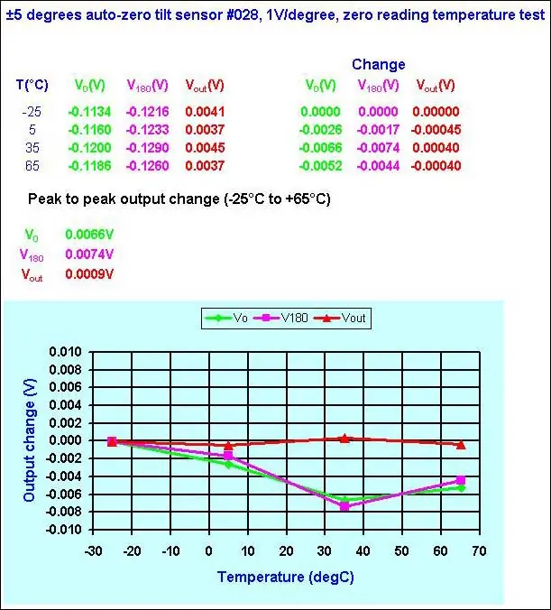
FIGURE 10 Typical temperature test results
Figure 9 shows the results of a typical temperature test of auto-zeroing operation in a single axis device. V0 and V180 are the direct readings from the internal servo-inclinometer at the two measurement positions for bias correction, while Vout is the computed result for bias correction. In this case, the internal sensor shows very low temperature sensitivity, about 0.007V maximum change over a 90oC range, which comes to 0.07%FR total for a +/-5V range (1V/deg), or 0.0008%FR/oC. Still, after bias correction the change is reduced to less than 1mV or 3 arc-seconds over the temperature range, well within the error range of the measurement equipment.
Summary
Servo-inclinometers reach high accuracy due to the closed loop principle used, plus predictable errors compensation. The random zero drift cannot be compensated, making difficult its use for low range tilt and leveling. This new device virtually cancels zero drift, even under harsh environmental conditions. Calibration is not required over unlimited periods of time, and consistent leveling accuracy of a few arc seconds is possible.
References:
US patents US6,546,639 US6,722,049